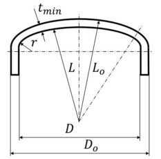
Torispherical heads with knuckle and crown radius are
adressed in paragraph UG-32 of ASME Code Section VIII,
Division 1. This special formula in the general UG part of
the ASME Code only applies to 6% heads whose knuckle
radius is 0,06 times Do. For all other torispherical heads
the general formula of Appendix 1-4(d) is used.
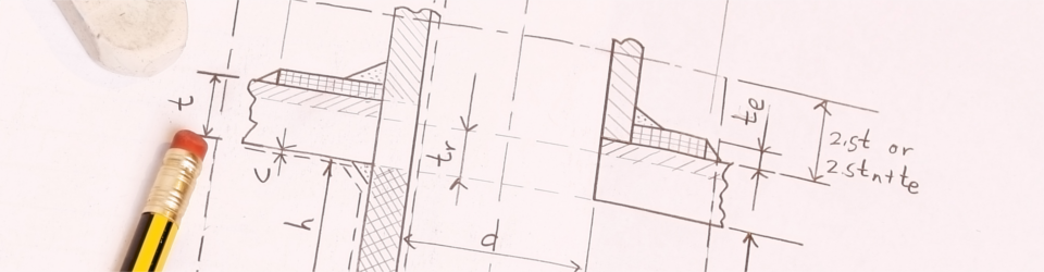
Please note that the minimum length requirements of the straight flange as shown in Fig. UW-13-1 sketch (l) and (m) must be met if the wallthickness of the heads exceeds that of the attached cylinder(min[3xth; 38 mm]). If, however, the head is inserted into a flange ring, the minimum length of the straight flange is addressed in Appendix 1, Fig. 1-6, sketch (a), i.e. insertion length + leg dimension of the fillet weld at the backface of a loose flange, and insertion length + leg dimension of the fillet weld + 13 mm for integral flanges respectively.
| P |
= |
MAWP + hydrostatic head |
| S |
= |
allowable stress according to ASME Code Section II, Part D |
| E |
= |
efficiency factor E = 1, if seamless and
meeting UW-11(a)(5)(b)
efficiency factor E = 0,85,
if not meeting UW-11(a)(5)(b)
efficiency factor
according to UW-12, if welded |
If you have further questions please contact us directly or start a discussion in our
ASME Code Forum. To stay informed about any changes and amendments to our websites, upcoming seminars and the latest information about the ASME Code, please feel free to subscribe our newsletter.
These calculation tools are intended to be used
for information and guidance only, they do not
replace a detailed design calculation and
compliance with all applicable Code requirements.
CIS GmbH expressly disclaims liability for errors
and omissions in the contents of this site.
 ASME Code Weeks (Online)
 ASME Code Wochen (Online)
 DE
DE NL
NL BE
BE FR
FR